
Cable length data helps understand payout/retraction status, repeated deployments, and maintenance usage. However, it describes the path the cable has traveled rather than directly measuring the aircraft's height above ground. Distinguishing between these two types of information reduces misunderstanding caused by numbers on the interface.
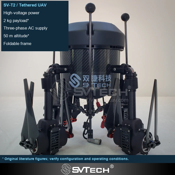
Measurements must be interpreted alongside geometric state
Payout length generally describes the amount of cable that has passed the measurement point, whereas the aircraft's height above ground is also affected by the ground path, offset, and sag. The two may correlate, but they cannot be treated as the same measured quantity.
Drum-diameter estimation, encoders, and independent length-measurement devices have different error sources. Slippage, tension, and cable lay can affect readings. Observing length together with flight altitude and platform position makes the actual state easier to understand. Cumulative payout/retraction totals can also become part of the maintenance record, helping to analyze usage intensity.
When verifying length, use a known-length reference and check different winding states and payout/retraction directions. If a deviation appears during retraction, also check for slippage, cable routing, and calibration settings.
Technical principles and engineering boundaries
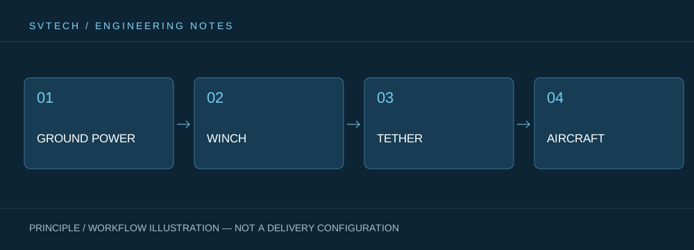
A tethered drone connects ground power, the payout/retraction mechanism, the cable, the flight platform, and the mission payload into one continuous system. When designing around "Making Cable Status Visible: The Practical Value of Length Measurement in Tethered Systems," power efficiency, cable weight, tension variation, payload cooling, and flight control all interact. A system cannot be described by maximum endurance alone; whether it can maintain stable service at a specified altitude, wind condition, payload power, and personnel rotation is what makes a continuously powered drone's capability meaningful in practice.
Application scenarios and implementation paths
Persistent observation, temporary communications relay, nighttime emergency lighting, and security in specific areas are all missions that a tethered platform may serve. They all require an aerial position to remain available over time, while each also imposes different requirements on imagery, links, illumination, or deployment speed. Incorporating mission objectives, ground power, the operating area, weather windows, and exit paths into the plan together can turn a tethered drone system from a demonstration device into an organizable on-site service.
Project validation and continuous optimization
To ground this technical discussion of "Making Cable Status Visible: The Practical Value of Length Measurement in Tethered Systems" in real projects, the validation phase should record configuration versions, environmental conditions, measurement positions, and mission results together. Define what the interface display quantity means, its permissible error, and the calibration procedure; altitude control should use the sensing and operating methods specified by the system; do not use an unconfirmed length value as the sole basis for obstacle avoidance. This information is not supplementary documentation but a shared basis for interpreting results, reproducing performance, and continuous optimization.
Related support from SV Tech
Zhuhai SV Tech Co. Ltd. provides product documentation, project requirement discussions, and configuration boundary checks for tethered drones and related industry applications. For topics such as "Making Cable Status Visible: The Practical Value of Length Measurement in Tethered Systems," you can describe the mission conditions, target outcomes, site environment, and existing equipment together, and Mr. Liu (+86 18688194199, lhc1983@gmail.com) will assist with coordination; specific models, performance, and delivery scope are subject to confirmed documentation and project validation.
Acceptance testing can compare against a known length under suitable ground conditions and repeat payout and retraction to observe cumulative deviation. Slippage, layer winding, and sensor calibration can all affect the display. The interface should clearly distinguish payout length from altitude, and operator training should also explain the relationship between the two so that a single reading is not treated as a complete positional basis.
A good data interface does more than present numbers; it also makes their meaning clear. The value of length measurement lies in supporting status assessment and long-term management.
