
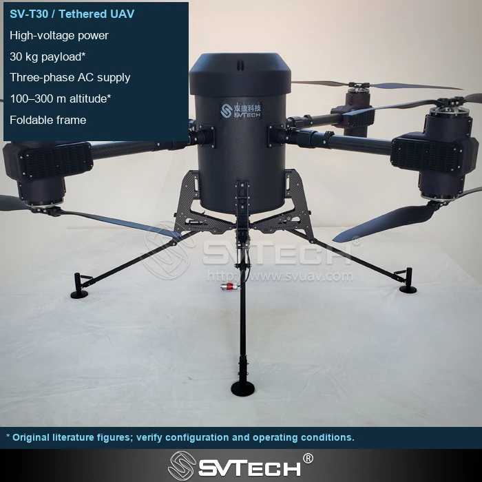
Define every load needed for the service
A tethered drone used for observation, emergency communications or lighting may draw power through a ground AC input, converters, cable, onboard supply and payload. The generator may also serve a winch, controls and cooling equipment. Separate continuous loads, intermittent movements and start-up events in the load schedule. Do not size from one instantaneous aircraft reading. Equally, the sum of equipment ratings is not automatically the measured operating demand: identify which figures are nameplate values, measurements or design assumptions.
Calculate losses within a consistent boundary
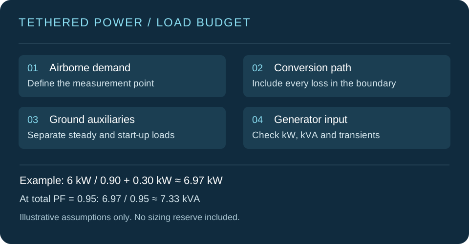
Starting with airborne DC demand, estimate upstream real power using the efficiency of the complete conversion path. For illustration, assume 6 kW is required at the airborne measurement point, overall efficiency from ground input to that point is 0.90, and separate ground auxiliaries draw 0.30 kW. Input real power is approximately 6 ÷ 0.90 + 0.30 = 6.97 kW. Efficiency must include every loss within that boundary. If cable or additional conversion losses are excluded, add them separately. These are worked-example assumptions, not performance claims for SV Tech products. Prefer measured whole-system input under the intended operating conditions.
Check both kW and kVA
Generator specifications often list real power in kW and apparent power in kVA; both limits matter. Continuing the example, a measured total power factor of 0.95 gives about 6.97 ÷ 0.95 = 7.33 kVA. This includes no sizing reserve. For nonlinear loads such as rectifiers and switching power supplies, use measurements that account for the actual waveform. Displacement power factor under an ideal sinusoidal assumption is not a substitute for total power factor. Also check voltage, frequency, single- or three-phase connection and the distribution of loads between phases.
Validate start-up and load changes
Converter energisation, winch movement and rapid airborne load changes can cause short voltage or frequency excursions. Adequate rated power alone does not show that downstream equipment will tolerate these events. Compare its allowable input range with the generator manufacturer's load-step response data, then validate the start-up sequence and representative changes under controlled conditions. Do not disable protection to conceal a mismatch. If buffer power is fitted, establish the loads it supports, its duration and transfer behaviour; the presence of a battery does not itself establish uninterrupted service.
The test wiring should represent the actual outlets, extension leads and distribution arrangement. Even with spare generator capacity, an individual branch or phase can reach its own limit first. If equipment repeatedly restarts, observe input voltage and load changes together rather than relying only on average panel power. Add equipment progressively and record the combination that triggers the problem to distinguish sustained overload, inrush and distribution mismatch.
Include environment and operating rating
Standby, prime and continuous ratings are different; select using the manufacturer's definitions and the actual duty. Temperature, altitude, ventilation and fuel conditions may reduce available output. Apply the derating data for the particular generator rather than a universal percentage. Extended missions also need arrangements for replenishment, maintenance, staff rotation and fault recovery. Locate ground equipment in accordance with its manufacturer's ventilation, exhaust, fuel and electrical-connection requirements. These constraints help determine whether sustained operation is practical at the intended site.
Connect selection to an acceptance record
Record no-load input, voltage and frequency as loads are connected progressively, steady-state power, representative load changes and temperatures during sustained operation. Establish acceptance limits from equipment requirements before testing, and identify instruments, measurement points and configuration versions. Zhuhai SV Tech Co. Ltd. can help check input interfaces and operating conditions against current documentation for the SV-T30 tethered system. Target height, airborne payload, service duration and the ground-load schedule define the power conditions to validate. The objective is an energy chain that works together throughout the mission, not simply a larger nameplate rating.
Business enquiries: Mr Liu, +86 18688194199, lhc1983@gmail.com.
