
The ground station enclosure can be compact, yet a complete mission still needs room for cable deployment, personnel operation and emergency response. If the field layout only reserves space according to equipment outlines, interference tends to appear once work begins.
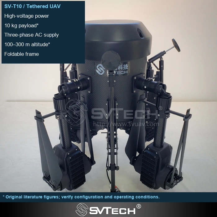
Space should be organized around movements and paths
Equipment outlines account for only part of the footprint. Actual deployment also includes cable entry and exit directions, operator positions, maintenance access, and power supply and take-off/landing zones. The working space left around the equipment affects emergency response capability.
Power replenishment, observation positions and maintenance access each have their own requirements, and the cable exit also needs an unobstructed path. If the public or vehicles still need to pass during operations, the layout must take these movement patterns into account. Describing the work area on a site plan in advance makes it easier for all parties involved to understand why the equipment needs a certain amount of space.
If the ground station is placed tight against a corner, the cable pay-out and retraction angle and the operator's path to the control panel may both be restricted. Routing cables through a pedestrian passage to save space also makes management more difficult.
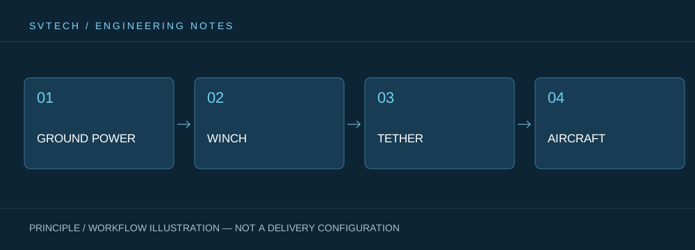
Technical principles and engineering boundaries
A tethered drone connects ground power, the pay-out/retraction mechanism, the cable, the flight platform and the mission payload into one continuous system. When designing around "Small Ground Station, Large Operating Footprint: Field Layout Logic for Tethered Systems", power supply efficiency, cable weight, tension variation, payload cooling and flight control all interact. The system cannot be described by maximum endurance alone; whether it can maintain stable service at a specified altitude, wind condition, payload power and personnel rotation interval is what makes a persistently powered drone meaningful in practice.
Application scenarios and implementation paths
Persistent observation, temporary communication relay, night-time emergency lighting and security for specific areas are all missions a tethered platform may serve. They all require a long-term available aerial position, while each places different demands on imagery, links, illumination or deployment speed. Incorporating mission objectives, ground power, operating area, weather window and exit routes into the plan together can turn a tethered drone system from a demonstration device into an organizable on-site service.
Project verification and continuous optimization
To ground this technical discussion of "Small Ground Station, Large Operating Footprint: Field Layout Logic for Tethered Systems" in real projects, the verification stage should record configuration version, environmental conditions, measurement positions and mission results together. Mark equipment, personnel and isolation zones according to the complete layout; reserve space for recovery and fault handling; verify against on-site dimensions before entry, not just equipment length and width. This information is not supplementary documentation but the shared basis for interpreting results, reproducing performance and continuously optimizing.
Related support from SV Tech
Zhuhai SV Tech Co. Ltd. provides product documentation, project requirement discussions and configuration boundary checks for tethered drones and related industry applications. For topics such as "Small Ground Station, Large Operating Footprint: Field Layout Logic for Tethered Systems", mission conditions, target outcomes, site environment and existing equipment can be described together, with Mr. Liu (+86 18688194199, lhc1983@gmail.com) assisting with coordination; specific models, performance and delivery scope are subject to confirmed documentation and project verification.
The actual space also includes cable entry and exit directions, maintenance access, personnel standing positions and emergency evacuation routes. The layout should account for ground station heat dissipation and protection, and the enclosure should not be squeezed into a narrow corner just because it is small. Site photos with dimensions and traffic directions are more helpful for confirming deployment feasibility than reporting only the available area.
Portability does not mean there are no site requirements. Describing equipment footprint and mission space separately improves deployment efficiency and helps customers prepare more thoroughly.
