
Continuous power lets a tethered platform carry more equipment, and it also brings power conversion and communication systems into closer proximity. Switching events, wiring and connection methods can affect signal quality; a module that performs correctly on its own is not enough to show that the combined system will be equally stable.
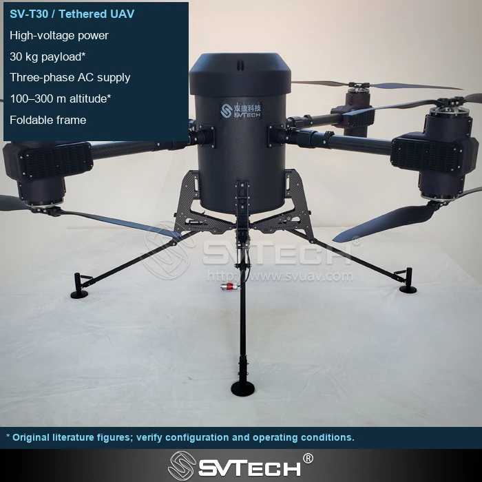
Layout Changes How Systems Interact
Switching power supplies, controllers and long cable runs can affect the electromagnetic environment, while signal-line routing and grounding methods also alter coupling. A good signal from a wireless device tested on its own does not mean the same performance will hold once the propulsion system and pumps are all running.
The distance between power and signal lines, the shape of current loops and the shielding connections all affect how interference propagates. Some problems appear only under high load or when a particular payload starts up, so a static power-on check cannot cover them. Observing power status and link quality together helps determine whether a fault stems from a shared operating condition.
If a communication problem occurs only within a certain load range, check power status and link quality at the same time. First establish the time correlation, then adjust wiring or filtering rather than swapping antennas at random.
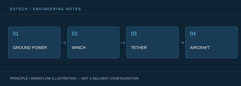
Technical Principles and Engineering Boundaries
A tethered drone links ground power, the tether management mechanism, the cable, the flight platform and the mission payload into one continuous system. When designing around "Coexistence of High Power and Wireless Signals: The EMC Challenge for Tethered Platforms", power efficiency, cable weight, tension variation, payload cooling and flight control all interact. The system cannot be described by maximum endurance alone; whether it can maintain stable service at a specified altitude, wind condition, payload power and crew rotation is the more meaningful capability of a continuously powered drone.
Application Scenarios and Implementation Paths
Persistent observation, temporary communication relay, night-time emergency lighting and security for specific areas are all missions a tethered platform can serve. They all require a long-available aerial position, while each places different demands on imagery, link, illumination or deployment speed. Bringing mission objectives, ground power, operating area, weather window and exit path into the plan together is what turns a tethered drone system from a demonstration device into an organizable field service.
Project Validation and Continuous Optimization
To ground this technical discussion of "Coexistence of High Power and Wireless Signals: The EMC Challenge for Tethered Platforms" in real projects, the validation phase should record the configuration version, environmental conditions, measurement locations and mission results together. Test with the final harness length, routing and connection methods; verify the payload and control link operating simultaneously; and have any change to filtering or shielding reviewed by qualified personnel and retested. This information is not supplementary documentation but the shared basis for interpreting results, reproducing performance and continuous improvement.
Related Support from SV Tech
Zhuhai SV Tech Co. Ltd. provides product documentation, project requirement discussions and configuration boundary checks for tethered drones and related industry applications. For topics such as "Coexistence of High Power and Wireless Signals: The EMC Challenge for Tethered Platforms", describe the mission conditions, target outcomes, site environment and existing equipment together, and Mr. Liu (+86 18688194199, lhc1983@gmail.com) will assist with coordination; specific models, performance and delivery scope are subject to confirmed documentation and project validation.
Record control link, video and positioning status separately at low load, high load and payload startup to identify anomalies related to power changes. Harness routing, shielding connections and equipment spacing can all change performance. A module that works in the lab is not sufficient on its own; final validation should be carried out under full integration and actual layout.
System integration must consider energy and information together. Only by placing compatibility validation within the real mission configuration can high-power endurance and stable communication support each other.
