
The longer the cable, the more carefully energy transmission must be designed. At the same transmission power, raising the voltage can reduce the current and thereby lower resistive losses; but insulation, conversion and connection requirements also change. The design of a tethered system is precisely about finding a balance between these benefits and costs.
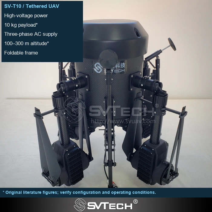
Electrical efficiency and flight burden are interlinked
Resistive loss is approximately I²R, and line resistance should include the complete loop and connection points. Rising temperature changes resistance, and actual voltage and current also vary with the mission, so a single-point estimate at room temperature is only a starting point.
Thicker conductors can reduce resistance, but they increase the cable weight borne in the air. A higher transmission voltage helps control current, but conversion efficiency and operating limits cannot be ignored. Final performance must be evaluated in combination with cable length, temperature and actual load, and cannot be derived from a single formula. Dynamic missions also cause the operating point to change continuously.
Assuming a loop resistance of 1 Ω and a current of 10 A, the line loss is 100 W; if the current increases to 20 A, the loss becomes 400 W. The example illustrates the current-squared relationship and does not represent the cable parameters of any actual model.
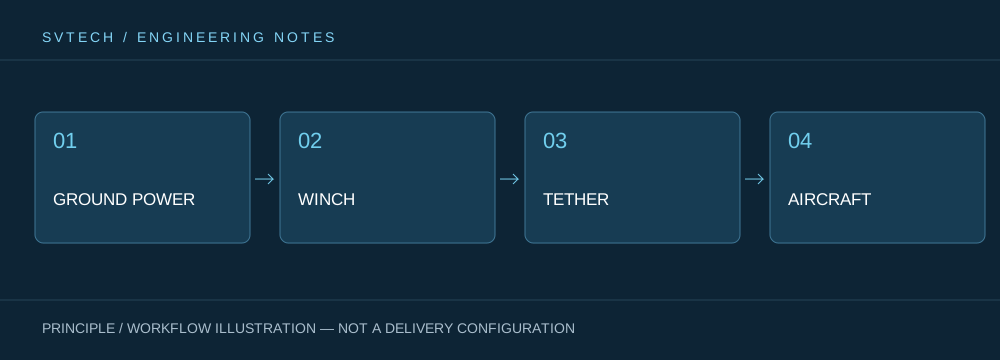
Technical Principles and Engineering Boundaries
A tethered drone connects ground power, the tether management mechanism, the cable, the flight platform and the mission payload into one continuous system. When designing around "High-Voltage Power Goes Airborne: Balancing Efficiency and Weight in Tethered Cables," power efficiency, cable weight, tension variation, payload heat dissipation and flight control all affect one another. The system cannot be described only by maximum endurance time; whether it can maintain stable service under a specified altitude, wind conditions, payload power and personnel rotation is the capability that is more meaningful for a continuously powered drone.
Application Scenarios and Implementation Paths
Persistent observation, temporary communication relay, nighttime emergency lighting and security for specific areas are all missions a tethered platform may serve. Together they require the aerial position to be available over the long term, and they each place different demands on imagery, link, illumination or deployment speed. Incorporating mission objectives, ground power, operating area, weather window and exit path into the plan can turn a tethered drone system from a demo device into an on-site service that can be organized.
Project Validation and Continuous Optimization
To ground this technical discussion of "High-Voltage Power Goes Airborne: Balancing Efficiency and Weight in Tethered Cables" in a real project, the verification stage should record the configuration version, environmental conditions, measurement locations and mission results together. Check the length, cross-section and connection status; measure the ground input, aircraft-end voltage and temperature rise under mission load. Keep the calculation assumptions and measured data separately. This information is not supplementary documentation, but the shared basis for interpreting results, reproducing performance and continuous optimization.
Related Support from SVTECH
SVTECH provides product documentation, project requirement communication and configuration boundary verification for tethered drones and related industry applications. For topics such as "High-Voltage Power Goes Airborne: Balancing Efficiency and Weight in Tethered Cables," you can describe the mission conditions, target outcomes, on-site environment and existing equipment together, and Mr. Liu (+86 18688194199, lhc1983@gmail.com) will assist with coordination; specific models, performance and delivery scope are subject to confirmed documentation and project verification.
As a preliminary approach, P_loss=I²R can explain DC resistive loss, but resistance changes with temperature and in practice also includes connection points. Calculations should specify the loop length and conductor conditions. On-site verification should measure both the input and the end-point status, and record the cable temperature; do not treat room-temperature estimates as the final result under long-term high load.
A good tether solution gives every gram of weight and every watt of loss a reason to exist. Understanding the relationship between voltage, current and cable is the key to reading system performance.
