
Scratches on the jacket not only indicate cable condition but also record where the cable has been in contact. Repeated wear at the same location may point to a guide component, a ground edge or a stowage method. Correlating these marks with deployment records helps improve the entire operating procedure.
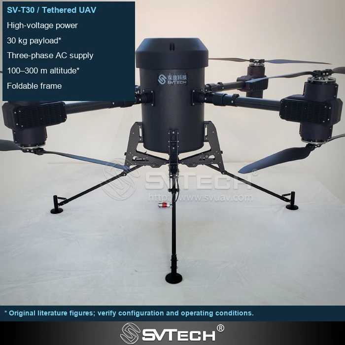
Maintenance can feed back into deployment improvement
The risk of jacket damage depends on location, depth, length and whether the internal structure is affected. \"It still powers up\" alone says nothing about insulation or load-bearing performance, and surface damage can also become a path for moisture ingress.
Replacing only the damaged cable does not necessarily eliminate the cause of the damage. Observing the contact location, wear direction and recurrence interval helps identify the load path. Decisions on continued use versus replacement should follow the specific cable and equipment requirements; a mark that looks minor does not allow any inference about internal condition. Spotting a trend early is more valuable than waiting for a failure.
If a cable keeps rubbing at the same guide point, the routing path must be corrected at the same time; otherwise a new cable will sustain the same damage. Field taping does not automatically restore the original electrical, mechanical or environmental ratings.
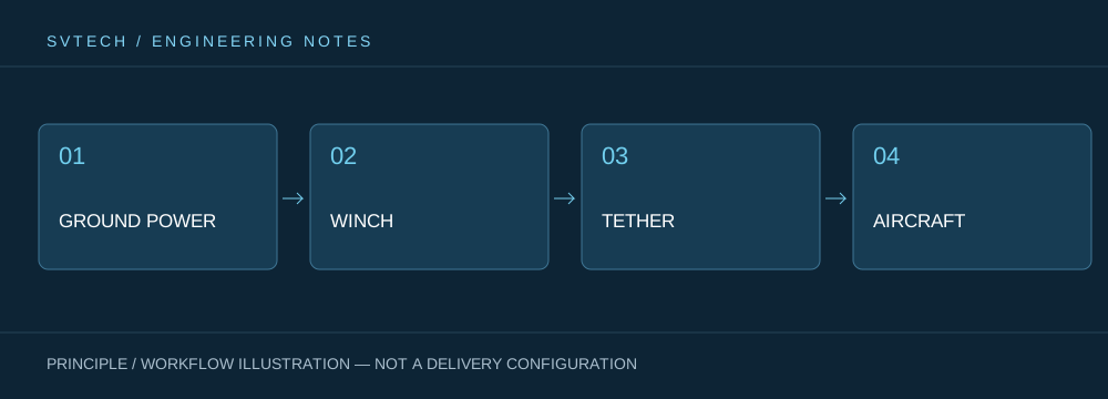
Technical principles and engineering boundaries
A tethered drone connects ground power, the tether management mechanism, the cable, the flight platform and the mission payload into one continuous system. When designing around \"Reading the Surface of a Tethered Cable: What Wear Marks Reveal About Field Conditions\", power efficiency, cable weight, tension variation, payload heat dissipation and flight control all interact. A system cannot be described by maximum endurance alone; whether it can maintain stable service at a specified altitude, wind condition, payload power and crew rotation schedule is the capability that matters most for a continuously powered drone.
Application scenarios and implementation path
Persistent observation, temporary communication relay, nighttime emergency lighting and security coverage of a specific area are all missions a tethered platform may serve. They share a requirement for long-term availability of the aerial position, while each places different demands on imagery, link, illumination or deployment speed. Bringing mission objectives, ground power, operating area, weather window and exit path into the plan together can turn a tethered drone system from a demonstration device into an organized field service.
Project verification and continuous optimization
To ground this technical discussion of \"Reading the Surface of a Tethered Cable: What Wear Marks Reveal About Field Conditions\" in real projects, the verification phase should record configuration version, environmental conditions, measurement locations and mission results together. Handle the cable according to the manufacturer's retirement and repair standards; isolate obviously damaged sections and retain photographs, length positions and event records. Do not continue trial use under load or splice the cable yourself without confirmation. This information is not supplementary documentation but the shared basis for interpreting results, reproducing performance and continuously optimizing.
Related support from SV Tech
Zhuhai SV Tech Co. Ltd. (SVTECH) provides product documentation, project requirement discussions and configuration boundary checks for tethered drones and related industry applications. For topics such as \"Reading the Surface of a Tethered Cable: What Wear Marks Reveal About Field Conditions\", you can describe the mission operating conditions, target outcomes, site environment and existing equipment together, and Mr. Liu (+86 18688194199, lhc1983@gmail.com) will assist with the coordination; specific models, performance and delivery scope are subject to confirmed documentation and project verification.
The maintenance log can record abrasion development by location with photographs, and check for flattening, kinking, exposed layers or abnormal heating. The conditions permitting continued use must follow the manufacturer's requirements; a visual judgment that the cable is \"not broken\" is not sufficient. If insulation damage is suspected, stop the related use and hand the cable over to personnel with the appropriate capability for inspection.
Every inspection can become a design feedback loop. Using wear information to adjust the field setup turns maintenance from reactive part replacement into continuous improvement.
