
The gimbal keeps the camera pointed in the right direction, while mechanical damping reduces the transmission of structural disturbances; the two address stability needs at different levels. Leaving all vibration to the gimbal or continually adding soft materials may not improve results. Stable imaging requires a complete understanding from the vibration source to the lens.
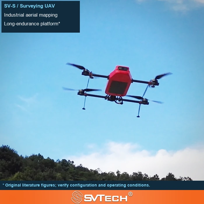
Disturbances in different frequency bands require different treatments
Damping must be matched to mass, frequency, and structure. Too soft may introduce low-frequency sway, while too hard may fail to isolate the target vibration; it also affects installation space and center of gravity.
Airframe attitude changes, power-cycle excitation, and mounting structure response have different characteristics. If poorly selected, a damping system may even amplify motion in certain frequency ranges. During verification, observe the image, motor speed, and payload mounting condition together; first distinguish the source of the problem, then decide whether control adjustment or mechanical improvement is needed.
If the original damping components are retained after changing the camera weight, the system dynamics may change. The data from the entire mission should be checked, not just whether the ground shake feels "soft".
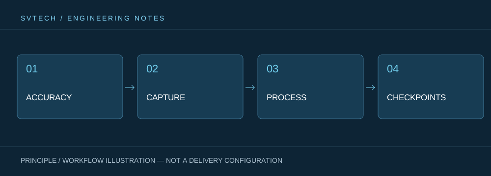
Technical principles and engineering boundaries
The capabilities of industrial UAVs are jointly determined by the flight platform, propulsion, sensing payload, communication, and data workflow. The phenomena discussed in "Engineering Foundations of Stable Imaging: How Gimbal Control and Mechanical Damping Work Together" often occur at the interfaces of these elements: a stable-flying platform does not guarantee deliverable data; and an algorithm that can identify a target does not mean the mission can proceed without human supervision. Only by placing performance back into the complete mission chain can we distinguish between a demonstration, repeatable verification, and long-term operations.
Application scenarios and implementation paths
UAV inspection, 3D modeling, emergency response, and asset management are all driving the low-altitude economy into industrial sites. Different applications require different flight paths, data quality, on-site collaboration, and compliance preparation. If the target object, deliverable format, operation frequency, site constraints, and exception handling can be clarified early in the project, it becomes easier to select suitable platforms and payloads for industrial UAV applications and to establish a sustainable data collection process.
Project verification and continuous optimization
To ground this technical discussion on "Engineering Foundations of Stable Imaging: How Gimbal Control and Mechanical Damping Work Together" in real projects, the verification phase should record configuration versions, environmental conditions, measurement positions, and mission results simultaneously. Confirm the adaptation range with the payload integrator and record mass and structure; check images and vibrations under representative operating conditions; retest after any change, and do not simply stack soft pads to solve problems. These records are not supplementary documentation but the common basis for interpreting results, reproducing performance, and continuous improvement.
Related support from SV Tech
SV Tech (SVTECH) provides product documentation, project requirement communication, and configuration boundary verification for industrial UAVs and related industry applications. For topics such as "Engineering Foundations of Stable Imaging: How Gimbal Control and Mechanical Damping Work Together", you can describe the mission conditions, target deliverables, site environment, and existing equipment together; Mr. Liu (+86 18688194199, lhc1983@gmail.com) will assist with the coordination. Specific models, performance, and delivery scope are subject to confirmed documentation and project verification.
The stiffness, mass, and frequency characteristics of the damping structure must match the payload. Too soft may introduce low-frequency oscillation, while too hard may transmit vibration. Keep the actual wiring harness and mounting attitude during testing, because harness tension can also change the effect; judgments should be based on both image and vibration data, not just feel.
High-quality images come from the cooperation of multiple elements. Letting the gimbal and damping each play their role is usually more effective than pursuing a more complex payload configuration alone.
