
The power performance of a drone is not determined by a single voltage on the motor nameplate. Taking off at full charge, climbing under heavy load, continuous hovering and decelerating descent all subject the power supply system to different states. Understanding these variations is what explains why the same motor set runs smoothly on the test bench but may trigger protection early once installed on the aircraft. Voltage design connects the battery, ESC, wiring harness and motor, and is the starting point for a power system to work in coordination.
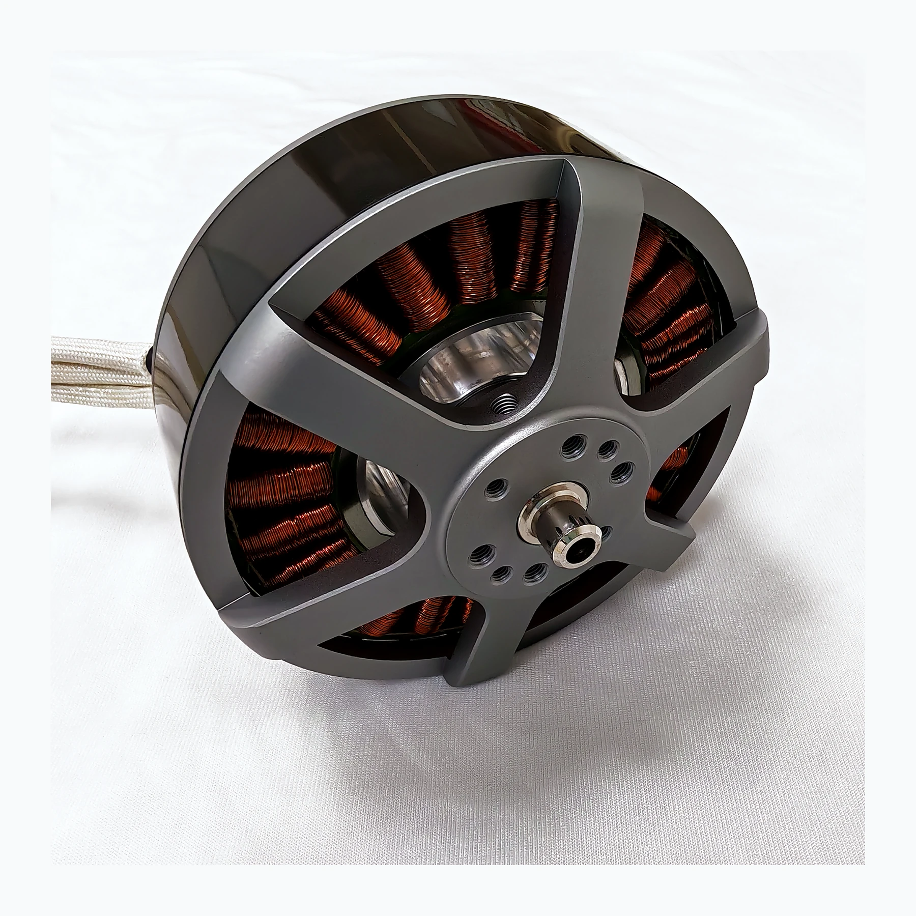
Finding a stable operating region within a varying power supply
Looking only at the battery's nominal voltage during selection misses the voltage variations at full charge, low charge and during braking regeneration. The motor, controller and power supply need a common permissible range, and short-term withstand values cannot be treated as continuous operating values. Systems with a large supply voltage drop should also verify the actual voltage at the far end, rather than only reading the power supply panel.
Raising the voltage can reduce bus current at the same input power, but the system does not automatically become more efficient as a result. The controller's operating range, the connector's insulation requirements and battery voltage drop all enter the design as well. What is truly meaningful is to plot the voltage trajectory of the entire mission, so that normal fluctuations always fall within the common permissible range. For inspection drones that need repeated takeoffs and landings, this design can reduce mission interruptions caused by protection actions, and also leaves a clear boundary for adding payload later.
Taking the 44.4–58.8 V DC range in the A32 manual as an example, a power supply showing 48 V at static state does not prove it stays within this range during a sudden load change. The startup, continuous load and rapid load reduction processes should be recorded, and the minimum and maximum values examined separately. This example only illustrates the matching method and does not infer a permissible overvoltage.
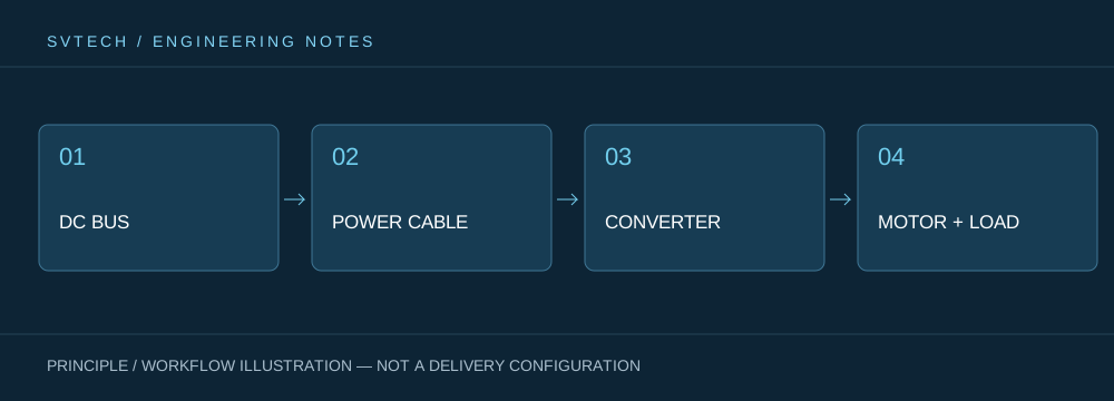
Technical Principles and Engineering Boundaries
A drone motor is not an isolated actuator component. The battery, ESC, windings, propeller and frame together determine how electrical energy is converted into lift and attitude control force. When discussing “From Battery to Propeller: The Voltage Design Logic of a Drone Power System”, the continuous operating point, short-term peak, heat dissipation path and installation forces should be viewed on the same mission curve: no-load speed, maximum current or single-item thrust can each describe only one side of it. For industrial drone power systems, reliably completing inspection, transport or hovering missions is usually more important than an extreme figure in a single bench test.
Application Scenarios and Implementation Paths
In applications such as surveying, inspection, logistics, and tethered platforms, power requirements change with payload, flight phase, and ambient temperature. Engineering teams can first determine the target thrust, the common cruise or hover range, and the allowable temperature rise, then review whether the supply voltage, KV, propeller, and control strategy match. This drone power selection process can also preserve clear technical boundaries for subsequent spare parts, maintenance, and upgrades.
Project Validation and Continuous Optimization
To make this technical discussion about “From Battery to Propeller: The Voltage Design Logic of a Drone Power System” applicable to a real project, the verification stage should record the configuration version, environmental conditions, measurement locations and mission results together. Submit the power supply's full output range and ripple information; verify the controller's undervoltage and overvoltage thresholds; confirm that margin remains after line losses. If the three do not have an overlapping window, the power supply scheme should be adjusted rather than trying to release protection through software. This information is not supplementary documentation, but the shared basis for explaining results, reproducing performance and continuous optimization.
Related Support from SVTECH
SVTECH provides product documentation, project requirement communication and configuration boundary verification for drone motors and related industry applications. For topics such as “From Battery to Propeller: The Voltage Design Logic of a Drone Power System”, mission conditions, target outcomes, site environment and existing equipment can be described together, and Mr. Liu (+86 18688194199, lhc1983@gmail.com) will assist with the connection; specific models, performance and delivery scope are subject to confirmed documentation and project verification.
Place the permissible conditions at the power supply end, controller input end and motor end in the same table, then mark the measurement time. For long-line power supply, the voltage drop at the far end should especially be examined, and in regeneration scenarios it must also be confirmed whether the power supply can absorb energy. If only a verbal answer of “48 V” is obtained, the documentation is still insufficient to freeze the scheme; upper and lower limits, transient conditions and protection action descriptions should be requested.
Power upgrades often begin with re-understanding the existing power supply. Only by restoring voltage from a static number into a curve that changes over time can the team judge whether to change the motor, adjust the wiring harness, or change the power distribution during the mission. A good power scheme gives these choices a solid basis.
