
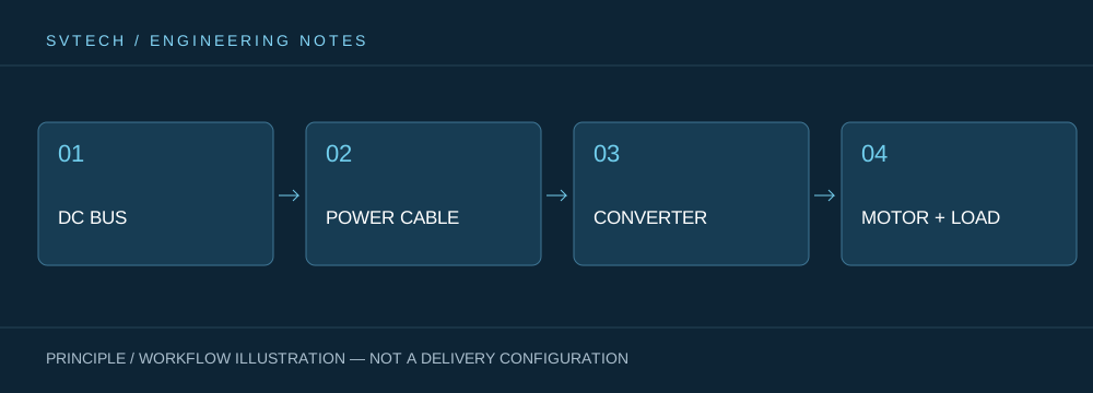
A motor draws electrical energy when accelerating; during deceleration, it may return part of the rotational system's energy to the supply side. In a propulsion combination with high inertia, rapid load reduction or braking causes the bus to experience conditions different from steady-state operation. Understanding where the energy goes helps explain how overvoltage events can occur even when the average voltage appears normal.
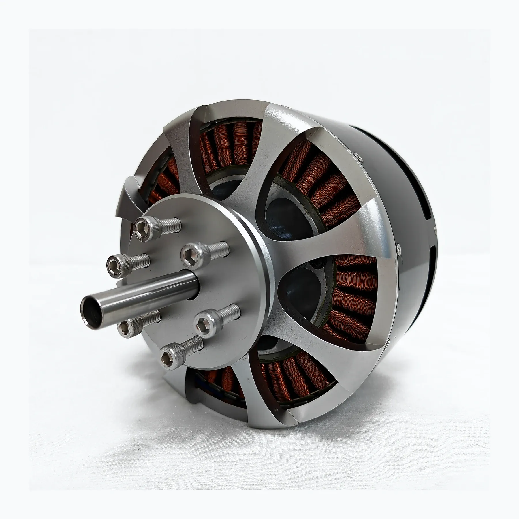
The power supply may not be able to absorb returned energy
The rotating system stores kinetic energy, and during deceleration part of that energy may return through the controller to the bus. If the supply does not accept reverse energy, the voltage rises. A protection trip does not necessarily indicate a motor fault; it may instead reflect an uncoordinated energy flow path in the system.
Laboratory power supplies, batteries and their protection systems differ in their ability to accept energy, so comparing only their output voltages is not sufficient. Control strategy, energy-storage elements and protection settings also affect transient behavior. Project validation should treat deceleration with the same rigor as acceleration, observing the complete transition rather than taking meter readings only under steady-state conditions.
The same motor may behave differently during deceleration when connected to a battery versus a laboratory DC supply. Testing should record bus voltage and the deceleration process, and confirm whether the controller has active braking enabled; steady-state no-load current alone is not enough.
Technical Principles and Engineering Boundaries
A drone motor is not an isolated actuator. The battery, ESC, windings, propeller and frame together determine how electrical energy is converted into lift and attitude-control forces. When discussing “Where Energy Goes During Deceleration: Understanding Motor Regeneration and Bus Voltage Changes,” the continuous operating point, short-term peaks, heat-dissipation path and installation loads should be viewed on the same mission curve: no-load speed, maximum current or single-point thrust each describe only one aspect. For industrial UAV propulsion systems, reliably completing inspection, transport or hover missions is usually more important than an extreme figure from a single bench test.
Application Scenarios and Implementation Path
In applications such as surveying, inspection, logistics and tethered platforms, propulsion requirements change with payload, flight phase and ambient temperature. Engineering teams can first define the target thrust, the typical cruise or hover range and the permissible temperature rise, then check whether the supply voltage, KV, propeller and control strategy match. This UAV propulsion selection process also establishes clear technical boundaries for subsequent spare parts, maintenance and upgrades.
Project Validation and Continuous Optimization
To ground this technical discussion of “Where Energy Goes During Deceleration: Understanding Motor Regeneration and Bus Voltage Changes” in real projects, the validation phase should record the configuration version, environmental conditions, measurement locations and mission results together. Confirm regeneration capability and protection schemes with the power supply and controller suppliers; validate according to the specified acceleration and deceleration profiles; do not disable overvoltage protection without authorization, and do not add uncalculated energy-dissipation components at will. This information is not supplementary documentation but the shared basis for interpreting results, reproducing behavior and continuously optimizing.
Related Support from SV Tech
Zhuhai SV Tech Co. Ltd. provides product documentation, project requirement discussions and configuration boundary checks for UAV motors and related industry applications. For topics such as “Where Energy Goes During Deceleration: Understanding Motor Regeneration and Bus Voltage Changes,” you can describe the mission conditions, target outcomes, site environment and existing equipment together, and Mr. Liu (+86 18688194199, lhc1983@gmail.com) will assist with the coordination; specific models, performance and delivery scope are subject to the confirmed documentation and project validation.
First distinguish between two scenarios: the load actively driving the motor, and a control command for rapid deceleration. Check the energy flow with the controller and power supply suppliers separately for each. If the supply does not accept reverse energy, the bus may require supporting energy-handling measures. The specific design should be verified according to the equipment scheme; do not add uncalculated resistors on an ad hoc basis or disable overvoltage protection.
Regeneration reminds us that power flow in the propulsion chain is not always one-directional. Clearly describing load changes and power supply characteristics makes system design more complete and avoids misinterpreting occasional protection trips as motor quality problems.
