
The battery current shown on the ground station reveals only part of the power system. The ESC organizes current in the three-phase windings to form the magnetic field that drives the rotor; the waveform and magnitude of these currents are not equivalent to the readings at the power supply end. Understanding this distinction can help engineering teams analyze low-speed heating, difficult starting and controller protection, and also makes discussions on motor and ESC matching more accurate.
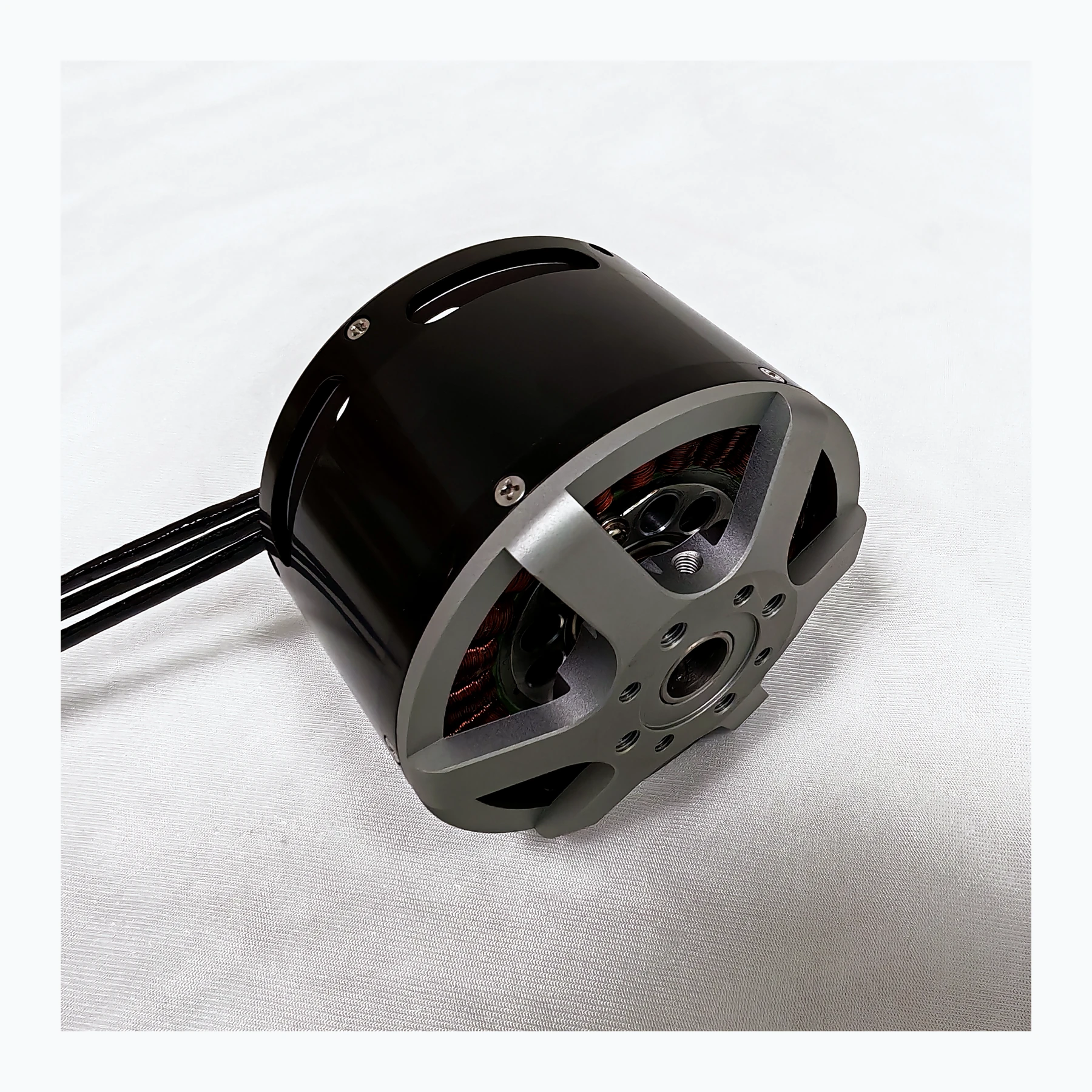
The two currents correspond to two observation points
The power-side current flows into the DC bus, while the motor phase current passes through the inverter switches and windings, with different meanings for waveform, RMS value and peak value. Under low-speed high-torque conditions, the phase current may be very high, while the average power supply current is not the same. Selecting a controller based on power supply current alone may underestimate the stress borne by the power devices and windings.
At low duty cycle or during rapid adjustment phases, the phase current may differ significantly from the bus current. If the battery-end average value is used to judge winding burden, local thermal stress may be missed. Modern control strategies focus on the direction, amplitude and rate of change of current; their value lies in making torque output more controllable, not in enabling any motor to exceed thermal boundaries. For heavy-propeller platforms, starting and sudden-change processes are especially worth observing separately, because these phases are often masked by long-duration average data.
If the manual gives a "rated input current," first confirm whether it refers to the power supply side or the phase line side. The 60 A marked by two controllers may also represent short-time peak and continuous RMS values respectively. The same number does not mean they are interchangeable; testing needs to distinguish continuous time and heat dissipation conditions.
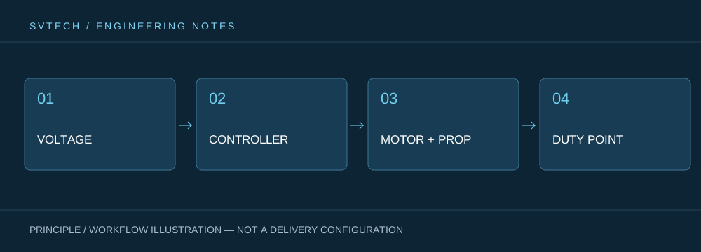
Technical Principles and Engineering Boundaries
A drone motor is not an isolated actuating component. The battery, ESC, windings, propeller and frame together determine how electrical energy is converted into lift and attitude control force. When discussing "Between ESC and Motor: How Ignored Phase Current Affects Power Performance," the continuous operating point, short-time peak, heat dissipation path and installation loads should be considered on the same mission curve: no-load speed, maximum current or single-item thrust can each describe only one aspect. For industrial drone power systems, stably completing inspection, transport or hover missions is usually more important than an extreme figure in a single bench test.
Application Scenarios and Implementation Paths
In applications such as surveying, inspection, logistics, and tethered platforms, power requirements change with payload, flight phase, and ambient temperature. Engineering teams can first determine the target thrust, the common cruise or hover range, and the allowable temperature rise, then review whether the supply voltage, KV, propeller, and control strategy match. This drone power selection process can also preserve clear technical boundaries for subsequent spare parts, maintenance, and upgrades.
Project Validation and Continuous Optimization
To make this technical discussion about "Between ESC and Motor: How Ignored Phase Current Affects Power Performance" applicable to real projects, the verification phase should record the configuration version, environmental conditions, measurement locations and mission results together. In the specification comparison table, list bus current, phase current and peak duration separately. Controller commissioning should be carried out by qualified personnel, observing temperature rise and protection records; do not use raising the current limit as an unverified method of increasing thrust. This information is not supplementary documentation, but a shared basis for explaining results, reproducing performance and continuous optimization.
Related Support from SVTECH
SVTECH provides product documentation, project requirement communication and configuration boundary verification for drone motors and related industry applications. For topics such as "Between ESC and Motor: How Ignored Phase Current Affects Power Performance," you can describe the mission conditions, target results, on-site environment and existing equipment together, and Mr. Liu (+86 18688194199, lhc1983@gmail.com) will assist with the coordination; specific models, performance and delivery scope are subject to confirmed documentation and project verification.
A, A rms and peak A in specifications should retain their original units and definitions, and should not all be written as "A" just for a tidy table. If the supplier only provides maximum current, you can ask further about the corresponding bus voltage, duration and cooling method. Commissioning records should also save the current-limiting strategy version, because the same hardware may have different allowable operating areas under different protection configurations.
The closer current monitoring is to the location where the problem occurs, the more effective the analysis. When purchasing matched power systems, having both suppliers clarify current definitions, measurement locations and time scales can improve system matching quality more than simply requiring an ESC with "higher current."
