
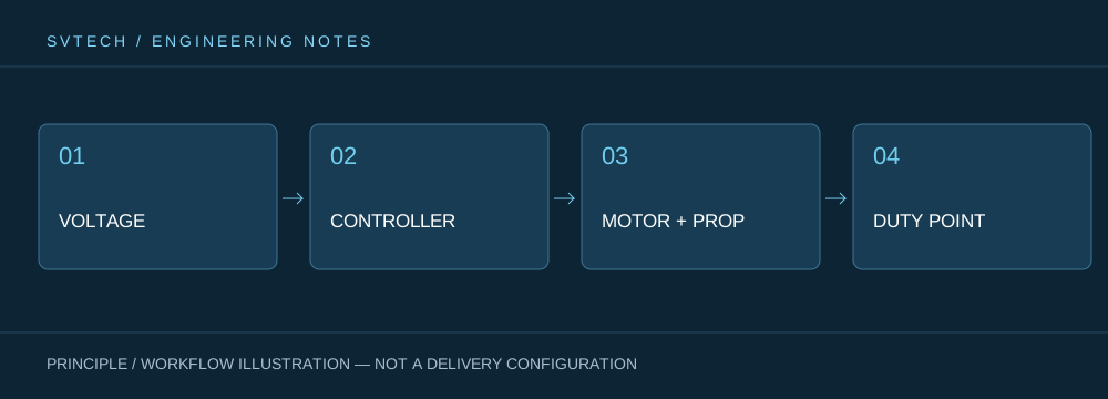
The power output from the battery becomes the aerodynamic force that lifts the aircraft only after passing through the ESC, motor, and propeller. Each stage has losses and is measured differently. As a result, two power systems with similar input power may produce different thrust; two aircraft with similar thrust may also have different endurance. Reading parameters along the direction of energy flow is closer to real performance than comparing maximum wattage in isolation.
Efficiency Should Be Understood Stage by Stage Along the Energy Chain
DC input power is approximately bus voltage multiplied by input current, and it includes losses in the ESC, motor, and connections. Shaft output power is related to torque and angular velocity, while thrust is also affected by the propeller and air conditions. The three describe different boundaries. The measurement location should be clearly stated in procurement tables to avoid treating power supply power as the motor's mechanical output.
The switching losses of the ESC, the copper losses of the windings, the magnetic circuit losses, and the aerodynamic losses of the blades occur at different locations. Using only DC input and static thrust, one can compare propulsion effectiveness under a given test condition, but cannot directly derive the mechanical efficiency of the motor itself. Surveying platforms often prioritize the mission benefit during hover or cruise, while transport platforms also need to consider takeoff peaks and heat dissipation. Evaluation metrics should serve these goals; otherwise, optimizing one number may shift the cost to another part of the system.
Suppose 50 V and 40 A are measured at the power supply end, giving an input of 2 kW; without torque and speed measurements, one cannot claim that the shaft power is also 2 kW. If two propeller-motor combinations have the same input but different thrust, the cause may lie in propeller efficiency and should not immediately be attributed to motor quality.
Technical Principles and Engineering Boundaries
A drone motor is not an isolated actuator. The battery, ESC, windings, propeller, and frame together determine how electrical energy is converted into lift and attitude control force. When discussing "How Electrical Energy Becomes Lift: Breaking Down the Three Conversions in a Drone Power Chain," continuous operating points, short-term peaks, heat dissipation paths, and installation loads should be viewed on the same mission curve: no-load speed, maximum current, or a single thrust value can each describe only one aspect. For industrial drone power systems, reliably completing inspection, transport, or hover missions is usually more important than a peak figure from a single bench test.
Application Scenarios and Implementation Paths
In applications such as surveying, inspection, logistics, and tethered platforms, power requirements change with payload, flight phase, and ambient temperature. Engineering teams can first determine the target thrust, the common cruise or hover range, and the allowable temperature rise, then review whether the supply voltage, KV, propeller, and control strategy match. This drone power selection process can also preserve clear technical boundaries for subsequent spare parts, maintenance, and upgrades.
Project Validation and Continuous Optimization
To make this technical discussion about "How Electrical Energy Becomes Lift: Breaking Down the Three Conversions in a Drone Power Chain" applicable to real projects, the validation stage should record the configuration version, environmental conditions, measurement locations, and mission results together. Record the sampling points for voltage and current, and confirm instrument bandwidth and calibration status; add torque measurement when shaft power is needed; standardize the ESC and propeller when comparing thrust efficiency. Inquiry documents should avoid using "power" without a clear boundary definition. This information is not supplementary documentation but the common basis for interpreting results, reproducing performance, and continuously optimizing.
Related Support from SVTECH
SVTECH provides product documentation, project requirement communication, and configuration boundary verification for drone motors and related industry applications. For topics such as "How Electrical Energy Becomes Lift: Breaking Down the Three Conversions in a Drone Power Chain," mission operating conditions, target outcomes, on-site environment, and existing equipment can be described together, and Mr. Liu (+86 18688194199, lhc1983@gmail.com) can assist with coordination; specific models, performance, and delivery scope are subject to confirmed documentation and project validation.
When comparing test reports, first draw the boundaries between the power supply, wiring, ESC, motor, and propeller. Power supply-end efficiency and motor-body efficiency are not the same metric. If the instrument recorded only battery output, the result should be named system input; if mechanical conversion efficiency needs to be evaluated, shaft-end measurement should be added, and the sampling times of torque and speed should be synchronized.
Recording power supply input, shaft-end output, and aerodynamic force separately is the first step in power optimization. This not only identifies real losses but also explains to customers that a larger power figure is only a capability boundary; the energy consumed to complete the same mission determines the long-term user experience.
