
Power optimization tends to focus on the motor and propeller, but the harness affects every flight just as much. Conductors, connectors and crimp points together form the power delivery path; a poor local contact not only generates heat but can also cause voltage fluctuations. Those seemingly insignificant connection details steadily erode system margin during high-current missions.
Resistance Distribution Determines Where Heat Occurs
Loop resistance includes the positive and negative conductors, terminals and connection contact surfaces; it cannot be calculated from conductor material alone. A poor contact can create a local hot spot, and this risk is especially pronounced in low-voltage, high-current systems; even a connector that looks intact can have crimping problems.
Thicker conductors can reduce some losses, but they cannot fix crimping or mating problems. If heat is concentrated near a connector, replacing the entire run with thicker conductors may not address the root cause. Comparing temperatures at each connection point against load changes can pinpoint anomalies faster. On multi-motor platforms, consistent harness workmanship also helps reduce differences between branches.
If the temperature at a terminal is significantly higher than the adjacent conductor, contact resistance can be checked using safe isolation and professional measurement procedures. Simply replacing the entire cable with a thicker one may not eliminate the hot spot while adding weight and bending burden.
Technical Principles and Engineering Boundaries
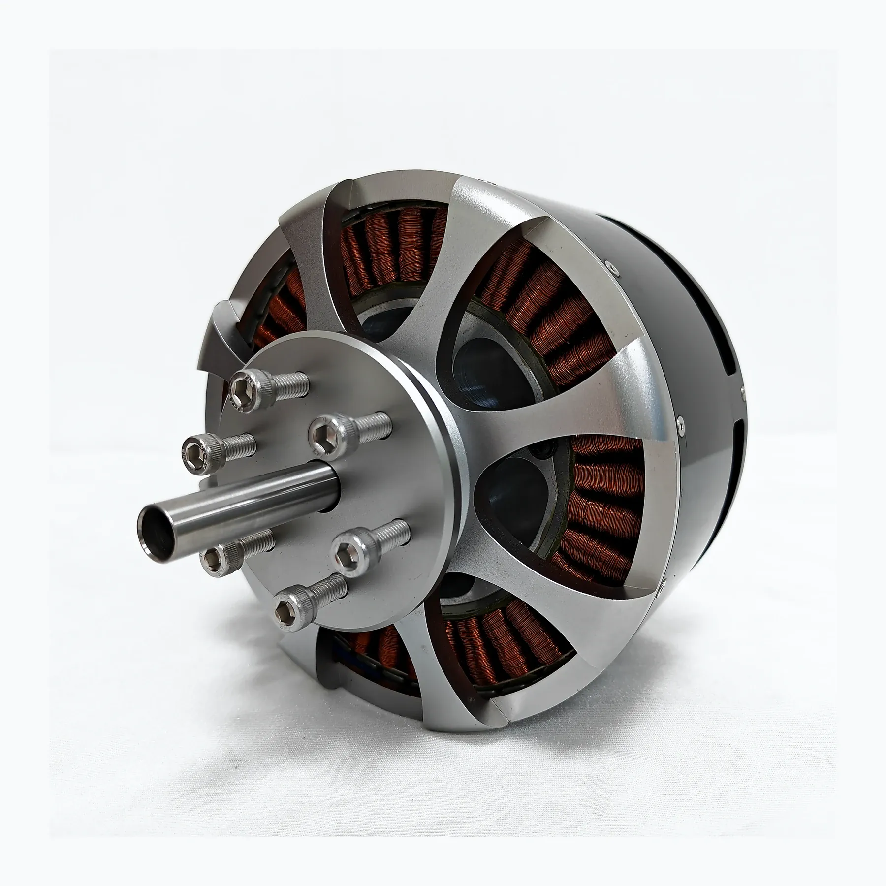
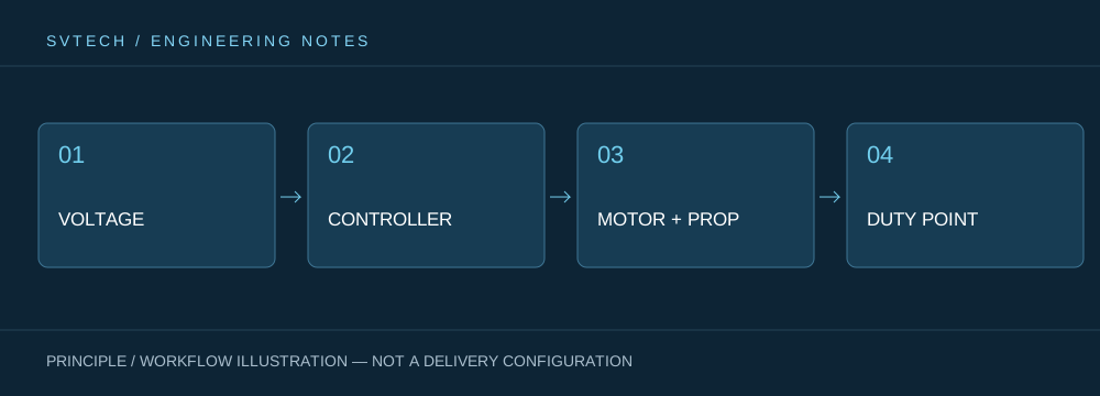
A UAV motor is not an isolated actuator. The battery, ESC, windings, propeller and frame together determine how electrical energy is converted into lift and attitude-control force. When discussing "The Endurance Hidden in the Harness: How UAV Power Systems Reduce Ineffective Losses", the continuous operating point, short-term peak, heat dissipation path and installation loads should be viewed on the same mission curve: no-load speed, maximum current or single thrust figure each describe only one aspect. For industrial UAV power systems, reliably completing inspection, transport or hover missions is usually more important than an extreme figure from a single bench test.
Application Scenarios and Implementation Pathways
In applications such as surveying, inspection, logistics and tethered platforms, power requirements change with payload, flight phase and ambient temperature. The engineering team can first define the target thrust, the usual cruise or hover range and the permissible temperature rise, then check whether the supply voltage, KV, propeller and control strategy match. This UAV power selection process also preserves clear technical boundaries for spare parts, maintenance and upgrades.
Project Validation and Continuous Optimization
For this technical discussion on "The Endurance Hidden in the Harness: How UAV Power Systems Reduce Ineffective Losses" to be applicable to real projects, the validation phase should record the configuration version, environmental conditions, measurement locations and mission results together. Select conductors according to actual current, length, environment and routing; verify that the crimping tool matches the terminals; and accept the complete loop voltage drop and local temperature rise, retaining connector batch and assembly records. This information is not supplementary documentation but the common basis for interpreting results, reproducing performance and enabling continuous optimization.
Related Support from SV Tech
Zhuhai SV Tech Co. Ltd. provides product documentation, project requirement discussions and configuration boundary checks for UAV motors and related industry applications. For topics such as "The Endurance Hidden in the Harness: How UAV Power Systems Reduce Ineffective Losses", the mission conditions, target outcomes, site environment and existing equipment can be described together, and Mr. Liu (+86 18688194199, lhc1983@gmail.com) will assist with coordination; specific models, performance and delivery scope are subject to confirmed documentation and project validation.
Voltage drop can be located by measuring section by section under the same load, but safe methods appropriate for the voltage level and environment should be used. Recording connectors, crimp points and long conductors separately avoids attributing all losses to wire gauge. After repair, re-measure joint temperature rise and voltage drop, and retain terminal specifications and process information for the next trend comparison.
A harness deserves to be designed, inspected and maintained like a power component. Incorporating connection reliability into whole-aircraft optimization can often yield more stable power delivery with smaller structural changes.
