
The connection between motor and frame may seem to be just a few screws, yet it withstands thrust, vibration, and repeated takeoffs and landings. Correct hole positions do not mean the installation is complete; screw insertion depth, contact surfaces, and locking methods all affect the outcome. For volume manufacturing, these millimeter-level details often determine product consistency more than a one-off performance demonstration.
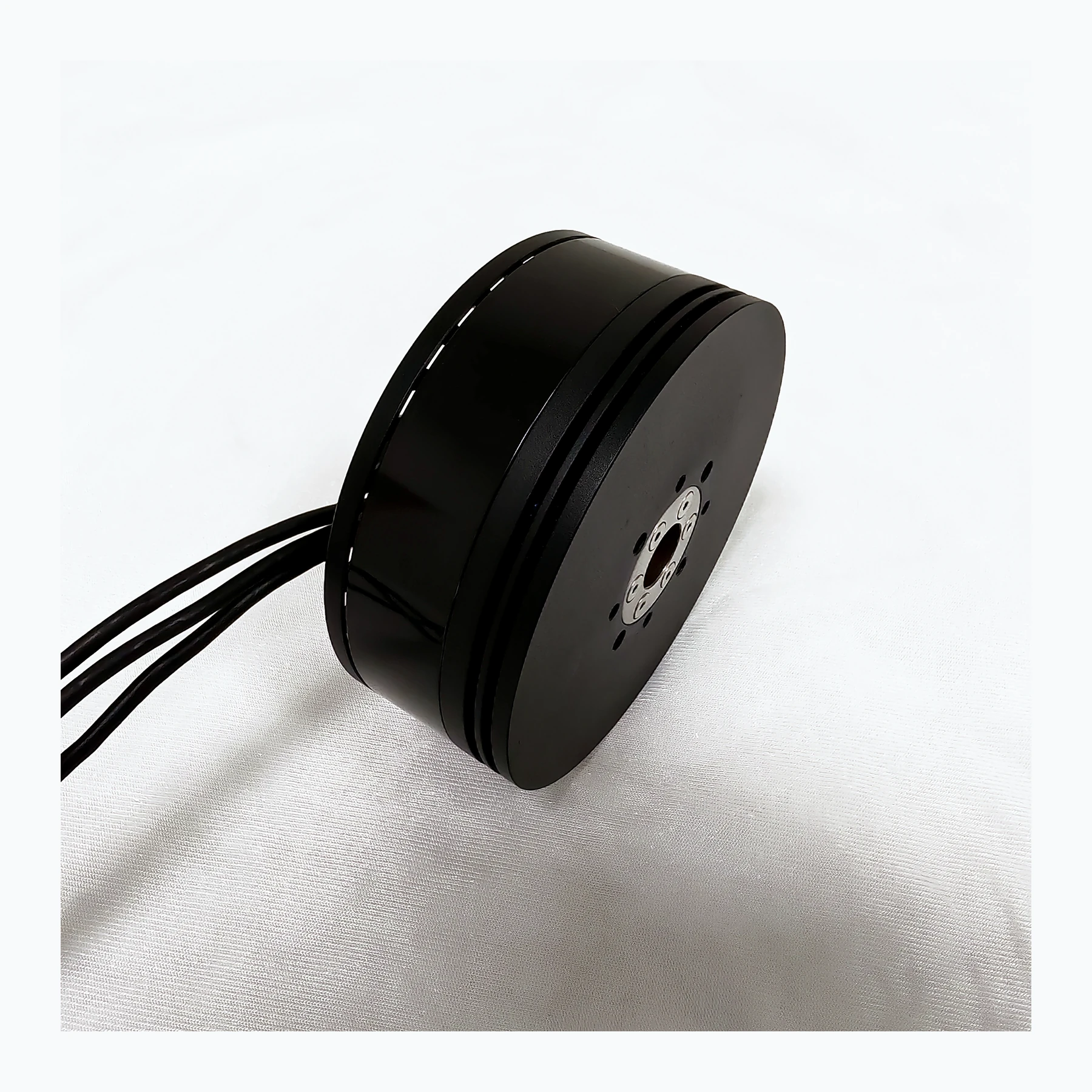
Mounting Depth Is a Design Dimension
The usable depth of the motor mounting holes is determined by the housing structure; long screws may contact the windings or internal moving parts. If common screws are selected solely based on bracket thickness, ignoring washers, tolerances, and thread engagement length, the assembly may suffer insulation damage or mechanical interference even when no problem is visible externally.
Effective engagement length and internal clearance must both be satisfied. Too short may compromise connection reliability, while too long may contact internal structures. After changing bracket thickness or washers, the original screws may no longer be suitable. Incorporating such changes into assembly drawings and process records can reduce the risk of on-site part substitutions based on experience, allowing design dimensions to truly carry over to production.
When calculating the length of screw entering the motor, subtract the bracket, washers, and effective clearance from the total length, and compare with the allowable value on the drawing. After bracket thickness varies between batches, this check must be redone; the same length cannot be reused just because it worked before.
Technical Principles and Engineering Boundaries
A UAV motor is not an isolated actuator. Battery, ESC, windings, propeller, and frame together determine how electrical energy is converted into lift and attitude control forces. When discussing “Reliability to the Millimeter: How UAV Motor Mounting Details Affect Airframe Performance,” continuous operating points, short-term peaks, heat dissipation paths, and mounting loads should be viewed on the same mission curve: no-load speed, maximum current, or single-point thrust each describe only one aspect. For industrial UAV propulsion systems, reliably completing inspection, transport, or hover missions is usually more important than an extreme figure from a single bench test.
Application Scenarios and Implementation Paths
In applications such as surveying, inspection, logistics, and tethered platforms, power requirements change with payload, flight phase, and ambient temperature. Engineering teams can first define target thrust, typical cruise or hover range, and allowable temperature rise, then review whether supply voltage, KV, propeller, and control strategy match. This UAV propulsion selection process also preserves clear technical boundaries for subsequent spare parts, maintenance, and upgrades.
Project Validation and Continuous Optimization
To ground this technical discussion on “Reliability to the Millimeter: How UAV Motor Mounting Details Affect Airframe Performance” in real projects, the validation phase should record configuration version, environmental conditions, measurement locations, and mission results together. Confirm thread specifications, maximum insertion depth, and fastening requirements according to the model drawings. First manually check assembly freedom, then tighten as specified. If friction or abnormal resistance is found, stop and investigate; do not attempt “run-in” under power. These records are not supplementary documents but the common basis for interpreting results, reproducing performance, and continuous optimization.
Related Support from SV Tech
SV Tech provides product documentation, project requirement communication, and configuration boundary verification for UAV motors and related industry applications. For topics such as “Reliability to the Millimeter: How UAV Motor Mounting Details Affect Airframe Performance,” you can describe mission conditions, target outcomes, site environment, and existing equipment together; Mr. Liu (+86 18688194199, lhc1983@gmail.com) will assist with coordination. Specific models, performance, and delivery scope are subject to confirmed documentation and project validation.
Assembly drawings should specify thread specifications, effective engagement length, and maximum insertion depth, while accounting for bracket thickness and washers. Spare screws of the same specification must also be checked for length tolerance. After removing fasteners, maintenance personnel should store them by position; mixing screws of different lengths can easily cause interference that would not otherwise exist during subsequent assembly.
The value of mounting design is to make correct assembly easy and repeatable. A clear dimension chain, appropriate tools, and traceable assembly records together support the long-term operational reliability of industrial UAVs.
