
Shaky aerial footage, frame resonance, and motor noise can all stem from the same vibration transmission path. Proper blade balancing is an important starting point, but vibration is also influenced by shaft-end runout, joint stiffness, and airframe structure. Industrial drones require smooth operation of the entire system, not just a single component passing inspection on its own.
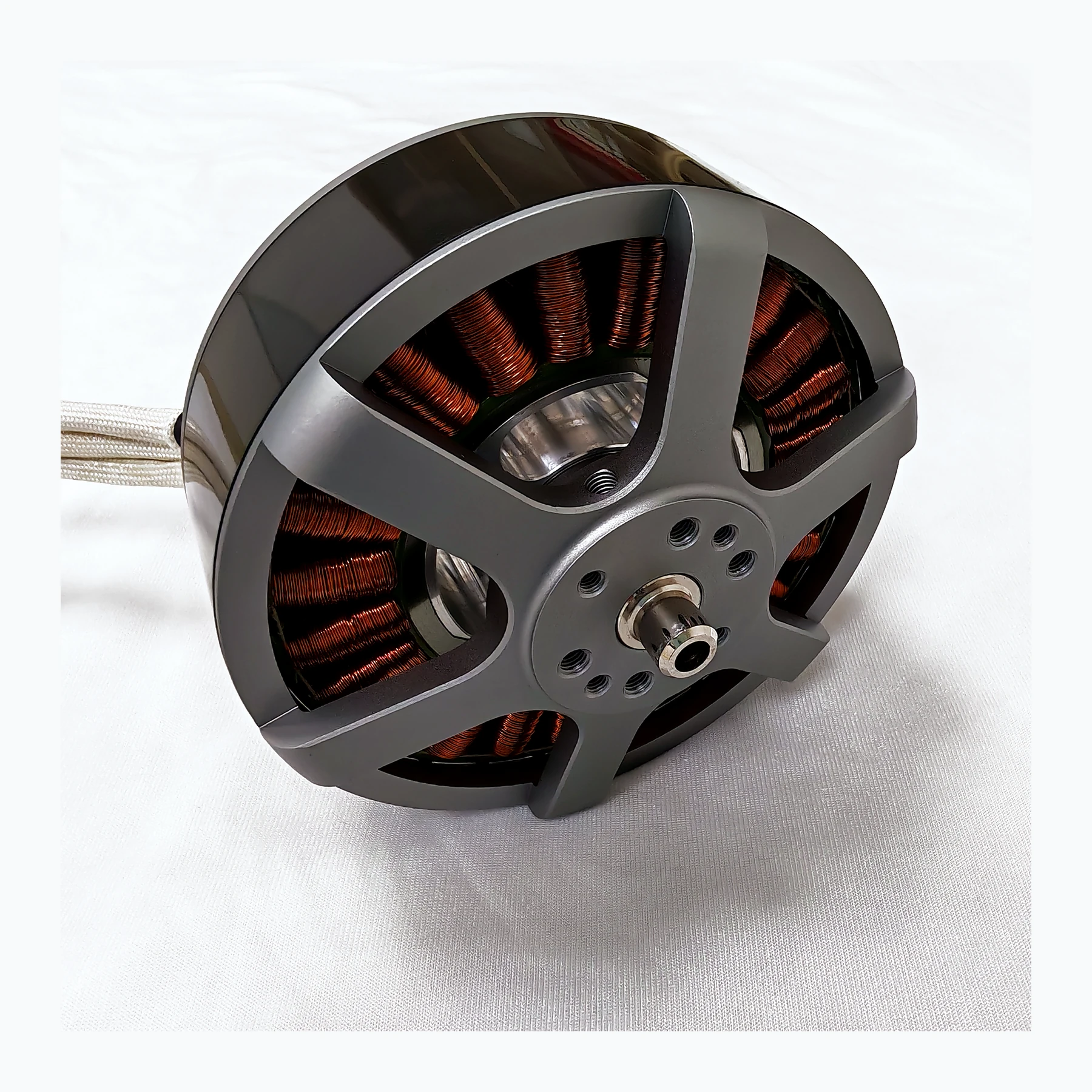
Vibration is amplified and transmitted along the structure
Static blade balancing only checks part of the mass distribution. The motor rotor, propeller mount, fasteners, and assembly eccentricity together affect the rotating system, and the arm structure may amplify specific frequencies. Therefore, "the blade is balanced" does not mean the powertrain is free of vibration, and smooth running at low speed does not guarantee smoothness across the entire speed range.
Rotating components generate periodic excitation, while the mounts and airframe each have their own response characteristics. When the excitation approaches a structurally sensitive range, even a modest disturbance can become pronounced. Simply adding damping material sometimes just moves the problem to another frequency band. A more effective approach is to observe how vibration changes with rotational speed, then combine that with the mounting condition to locate the source, so that the powertrain, structure, and payload damping each play an appropriate role.
If vibration is pronounced only in a certain speed range, record the relationship between frequency and rotational speed, then check the mounting surface, propeller-mount runout, and structural resonance. Simply adding soft pads sometimes only shifts the resonance position and may affect fastening reliability or the heat dissipation path.
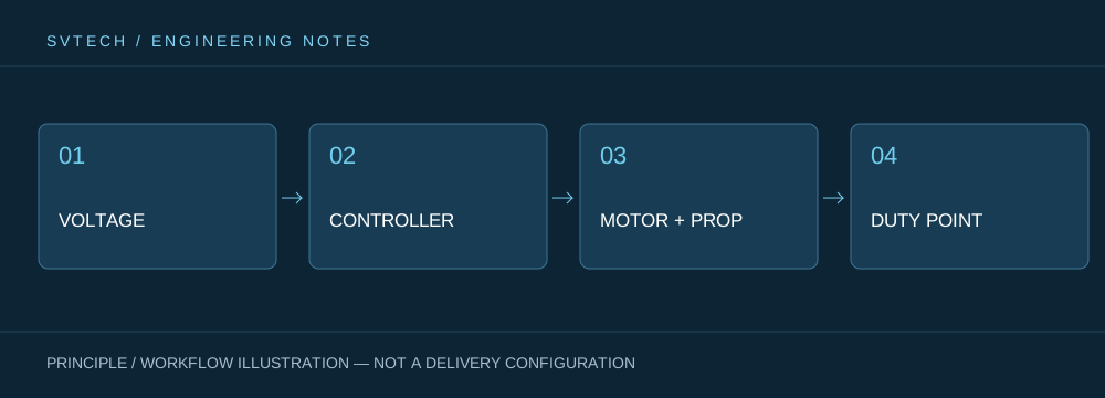
Technical principles and engineering boundaries
A drone motor is not an isolated actuator. The battery, ESC, windings, propeller, and frame together determine how electrical energy is converted into lift and attitude-control force. When discussing "Making Drone Footage More Stable: From Blade Balancing to Whole-Aircraft Vibration Control," continuous operating points, short-term peaks, heat dissipation paths, and mounting loads should be viewed on the same mission curve: no-load speed, maximum current, or single-point thrust each describe only one aspect. For industrial drone powertrains, reliably completing inspection, transport, or hover missions is usually more important than an extreme figure from a single bench test.
Application scenarios and implementation path
In applications such as surveying, inspection, logistics, and tethered platforms, power requirements change with payload, flight phase, and ambient temperature. Engineering teams can first define the target thrust, the usual cruise or hover range, and the allowable temperature rise, then review whether the supply voltage, KV, propeller, and control strategy match. This drone powertrain selection process also leaves clear technical boundaries for subsequent spare parts, maintenance, and upgrades.
Project validation and continuous optimization
To ground this technical discussion on "Making Drone Footage More Stable: From Blade Balancing to Whole-Aircraft Vibration Control" in real projects, the validation phase should record the configuration version, environmental conditions, measurement locations, and mission results together. First verify that components are undamaged and assembly torque is correct, then carry out stepped speed tests. Keep acceleration data and mounting methods, and if necessary, commission professional dynamic balancing. Do not perform on-site "rebalancing" by grinding motor structural parts. This information is not supplementary documentation but the shared basis for interpreting results, reproducing performance, and continuously optimizing.
Related support from SV Tech
Zhuhai SV Tech Co. Ltd. provides product documentation, project requirement discussions, and configuration boundary checks for drone motors and related industry applications. For topics such as "Making Drone Footage More Stable: From Blade Balancing to Whole-Aircraft Vibration Control," you can describe the mission conditions, target outcomes, on-site environment, and existing equipment together, and Mr. Liu (+86 18688194199, lhc1983@gmail.com) will help with coordination; specific models, performance, and delivery scope are subject to confirmed documentation and project validation.
Troubleshooting can establish a baseline in sequence—blade, propeller mount, motor, mount, and whole aircraft—while keeping measurement locations consistent. A sudden increase in vibration at a certain speed may indicate structural resonance, not just mass imbalance. If damping components have been replaced, observe the control response and image stability again to avoid solving one frequency band while introducing another problem.
A smooth powertrain improves image quality and also makes maintenance decisions clearer. Continuously recording the vibration signature of the same configuration helps distinguish normal operating characteristics from gradually emerging mechanical changes.
